Electron Beam Evaporator
Background
As part of the Sánchez Nano Development Lab at Portland State University, I teamed up with fellow undergraduate student Ryan McGraw to rebuild a 10 kV electron beam evaporator that had long ago been mothballed from its original industrial use case and donated to the lab. The system was found in an unknown state, requiring us to approach all subsystems as potentially faulty. Over the course of a year, we rebuilt the E-beam, ultimately achieving a copper coating and paving the way for Ryan's continued use of the system in his graduate studies.
Repairs Undertaken
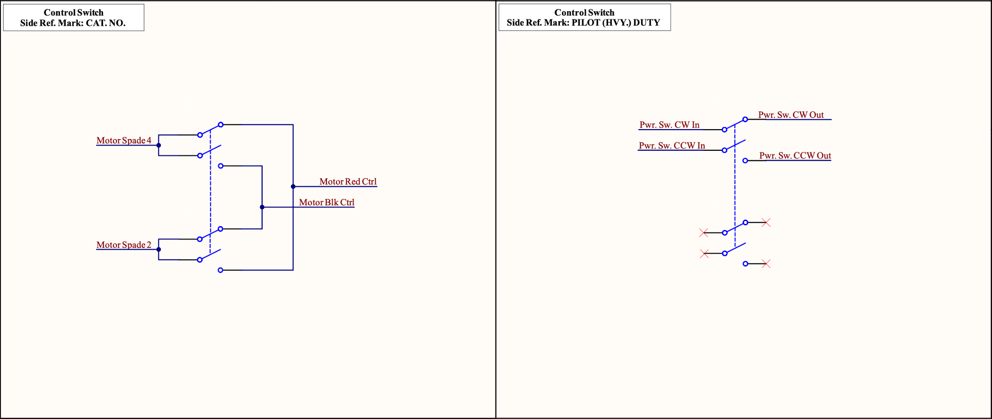
The system in question was inherited with multiple subsystems incomplete or not functioning. Most obviously, the chamber was initially rendered inaccessible by the failure of a lift system for the attached vacuum bell jar. Resistance testing of the driving motor quickly indicated a break in one of the windings, and a replacement 1/3 horsepower NEMA 48N frame oil burner motor with reversible rotation direction was obtained, and wired directly to a 4-way DPST switch according to Fig. 2.
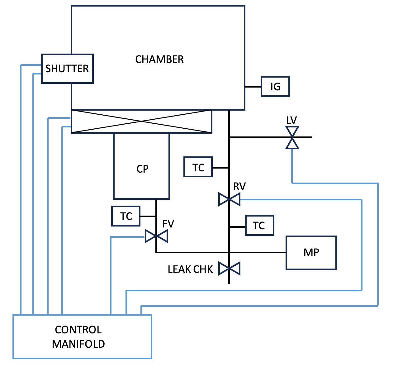
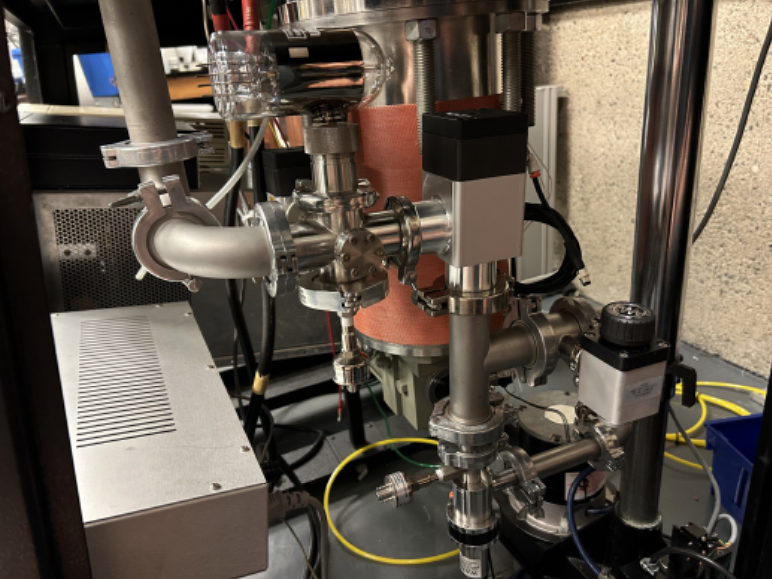
Next, the existing, partially complete vacuum system was stripped off. The roughing system was rebuilt using Kwik Flange components, according to Figs. 3 and 4. An Edwards dry scroll pump was attached to achieve a rough vacuum of 10−3 Torr, and to regenerate the attached cryopump as necessary.
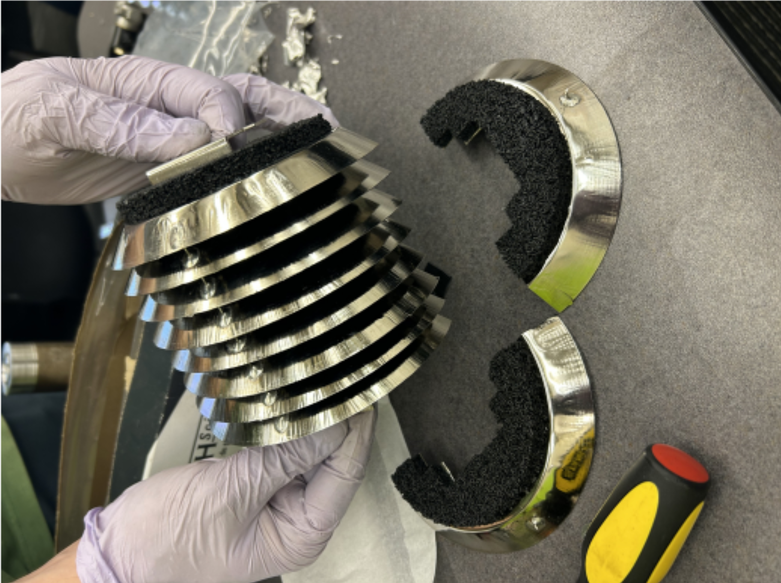
The CTI cryogenics CryoTorr 8 cryopump used on the original system was disassembled to inspect for damage. While the top 80 K condensing array was found to be intact, the lower 15 K adsorbing array sustained significant damage in previous use, with large chunks of the carbon coating on the arrays found detached. New arrays were adapted to fit the system using a rotary cutting tool, as shown in Fig. 5.
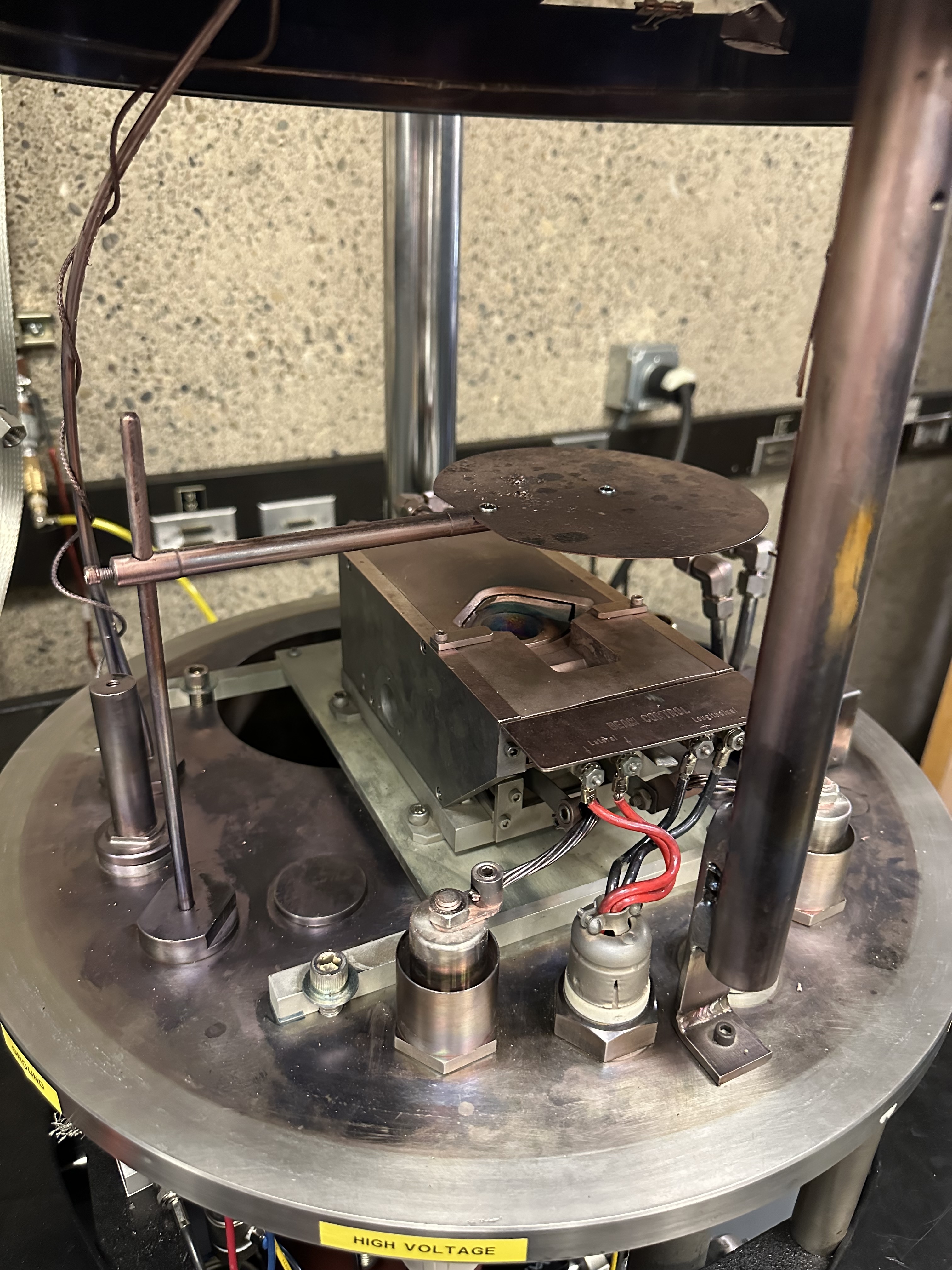
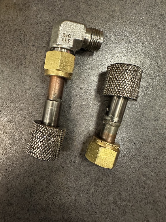
The high vacuum valve was removed and replaced with a newer valve with the same ISO 8-inch flange before remounting the cryopump. A CTI 8200 compressor was attached, and the helium lines were recharged to 250 PSI. The pump was regenerated for around ten hours using the heat blanket seen in Fig. 4 and the scroll pump to evacuate deadsorbed gasses. The subsequent ultimate pressure achieved on the chamber after roughly 24 hours of pumping was 1.7 × 10⁻⁶ Torr. To control the valves, a pneumatic manifold was implemented, with toggle-switch controls soldered for manual operation of the system. At this point it was possible to install the E-gun in the chamber. A mounting plate was machined for the gun, and 3/8 inch copper water lines were fitted with Swagelok ferrules to create a secure connection with the vacuum feedthrough. The lines’ overall integrity was assessed by attaching individual sections to a mechanical pump, and testing with a helium leak checker. A major leak was discovered at the brazed joint that adapts the gun’s knurled water connections to Swagelok, likely due to inadequate solder penetration. Replacement adapters were radially welded to ensure durability, and upon installation the water lines passed all additional leak checking tests.
With the E-gun installed, the chamber needed an adequate ground. Given the location of the system within the building, it was impractical to follow the manufacturer’s suggestion of installing dedicated earthing rods to establish a ground path, and a braided metal strap was instead bolted to a girder in the ceiling, which was found to have less than one ohm resistance when measured against the ground of a trusted nearby three-phase outlet. The other end of the strap was bolted to a stud on the base of the chamber, and a short, direct run of 6 AWG copper wire was used to connect this chamber ground to the power supply. In an effort to build redundancy and to ensure the lowest possible impedance path from the power supply to ground, the finish was ground off the frame at a point near the power supply using a flap disc, and a braided strap was bolted between the supply and the bare metal. The resistance from the supply to the chamber with the other ground wire disconnected was measured at less than one ohm.
The Airco Temescal ES-6 power supply on the system was missing its original start key, so a suitable 120 V, 15 A toggle switch was connected in place of the keylock. System interlocks and longitudinal sweep con-trol for the supply were routed to the chamber in a 16-gauge cable bundle terminating in an Amphenol-style plug at the supply. A DIN rail was mounted on the system’s front panel and fitted with terminal blocks, creating a central point for connectivity between the interlock cable, control switches, and monitoring systems. The negative longitudinal lead on the sweep control electromagnet was connected to the power supply output cable through the terminal blocks, and the positive lead was connected to the chamber ground. In addition to the chamber pressure interlock and the water flow interlock described below for the power supply, a normally-open relay in the vacuum gauge controller was connected in series with the isolation valve switch and programmed to close only at pressures below 1×10⁻³ Torr to prevent accidental air dumps.
To establish adequate cooling water flow, an S&A chiller was attached to the water lines, along with an SMC flow switch with attached readout to establish the water flow interlock. A pneumatic quarter turn actuator attached to a rotary vacuum feedthrough was used to implement a shutter to block the melt from the substrate between coatings.
Finally, a Microdot cable was used to connect the thin film crystal head within the chamber to its feedthrough, and an oscillator was connected with a short BNC cable to the external side of the feedthrough. The oscillator was then connected to a Maxtek MDC-260 deposition controller to monitor coating thickness.
During the repair process, the chamber was occasionally pumped down to ensure continued vacuum integrity. At certain points while pumping the chamber, the cryopump was found to make a ratcheting noise while the yoke stuttered in the sight glass, an indication of helium contamination in the compressor circuit. To prevent damage to the pump, the system was turned off until the helium circuit could be decontaminated, and was turned back on 24 hours prior to servicing to trap contaminants in the cold head. During servicing, the helium lines were disconnected from the compressor, and the oil adsorber was replaced. The cryo was allowed to return to room temperature before the helium in the lines was replaced. The issue was resolved following this decontamination procedure.
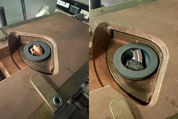
With the system in operating condition, the flow rate was tested to determine whether the chiller could supply the 3 GPM required to operate the gun at full power. It was found that output averaged only about 2 GPM, leading to the decision to test the system only below 100 mA of beam current, or roughly 17% of the system’s peak power. Fig. 7 shows the crucible before and after an initial run, with copper pieces exposed to the beam for less than one minute at low current.It was noted in this initial run that the chamber pressure increased to such a degree that the vacuum interlock was tripped at one point, a likely indication of the need to bake out the chamber to vaporize contaminants that would otherwise enter the gas phaseunder vacuum. While the seals on the system are not of a heat tolerant material such as Viton, a lower-temperature bake could be performed using only a heat gun. Future testing will indicate the efficacy of this method as compared to running the gun at low power before a coating to bake out the gun and the chamber.
A planetary substrate holder must also be installed to ensure even coatings by rotating substrates above the vapor source. Future research will require the installation of an optical feedthrough for a spectrometer, which will be configured to determine coating thicknesses and optical characteristics. A stepper motor will also be installed to rotate between the hearths of the crucible during coatings to achieve complex, multi-layer thin films based on spectroscopic endpoint detection. Ryan's dissertation, which provides further theoretical detail on spectroscopic endpoint detection, can be found here.